In practice a simple NDT method that is most used on site for in-service inspection to locate wall loss due to corrosion / erosion etc. For UTT to be effective requires a very careful attention to detail. This has been recently recognised by National Standards where previously it was considered a ‘UT thickness measurement’ is now by recognising the difficulty, been amended to a ‘UT thickness determination’. Being involved with NDT over the years this has generally been the technique that has the potential for the most likelihood of a mistake to be made. Below I have listed 10 areas where we might get tripped up, you will probably be able to think of a few others:-
(i) The appropriate location – since ultrasonic thickness testing is in the majority of cases a % check you need to make sure you are checking in the right area on the pipe, vessel etc. Some agreed specific guidance should be provided in the UTT procedure.
(ii) If it is a repeat inspection (every so many years) make sure you get sight of the previous UTT report before you test.
(iii) The surface you are UT testing on needs to have a clean and even contact area with any loose or non adherent coatings removed.
If its an external pipe scab (corrosion blister a build up of corrosion scale) leave well alone as its removal could result in a loss of containment as the area under the pipe scab can be corroded almost through the material thickness.
Removal of corrosion blisters shall not be undertaken without the expressed permission, authorisation and co-operation of the client. The client must assess the risk to personnel and the environment prior to removal of corrosion blisters.
Example: See radiographic profile image which indicates below pipe scab the pipe wall thickness is close to only 1mm of sound metal remaining.
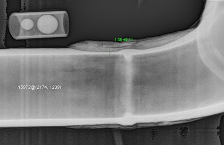
Pipe thinning adjacent to weld
(iv) If you are taking a UT reading on surfaces that may not be parallel a UT set with only a digital read out is not suitable. These sets would be o/k for new material where both sides are parallel but once you are applying the technique in service then wall loss is possible and a digital reading with an accompanying ‘A’-scan display should be applied.
(v) Is the surface you are testing painted and displaying good adhesion to the surface? When testing through paint have you allowed for this in your readings ? Paint has a slower acoustic velocity compared to steel which means a thin coating of paint can make a significant difference to your thickness measurement. So exclude the paint from your measurement by measuring between your 1st and 2nd backwall signals.
(vi) If internal pitting is detected or suspected your measurement should be up to 1st backwall signal.
(vii) Do we have the right diameter probe for the size of pipe and also the optimum probe for the anticipated thickness and another back-up probe for the unanticipated thickness. For example a 5Mhz 10mm dia. twin may work best around 10mm but if you detect changing wall loss that begin to reduce your readings sharply down over you may need to consider changing your probe to complete the survey.
(viii) When using a twin crystal probe on pipework, particularly small diameter pipework, make sure you have the probe axis aligned ninety degrees to pipe.
(ix) If carrying out an in-service thickness check is the item at ambient temperature or is it hot. The hotter the pipe above ambient the UTT readings will become (a) slower and give a thicker reading than actual approximately 1% per 55 degrees centigrade and (b) provide a higher signal to noise ratio which means you may have to increase your gain. UTT at high temperature will never be as accurate as at ambient.
(x) When you pick up readings that occur intermittently less than the back wall signal is this wall loss from pitting or could it be material inclusions ? Are you able to check for the difference by using an angle probe ?
