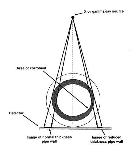
When carrying out tangential radiography to BS EN 16407 (Radiographic Inspection of corrosion deposits in pipes by X and Gamma Rays) an example of a typical set up is shown below where the pipe wall at certain positions can be imaged. With this technique it is important to ensure you get the set up right ( see radiographic image below).
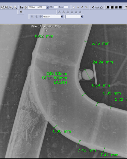
On viewing this image there appears no indication of pipe wall loss at the extrados.
When the pipe connection was re-radiographed (see below) the resulting image clearly showed evidence of wall loss at the extrados!!
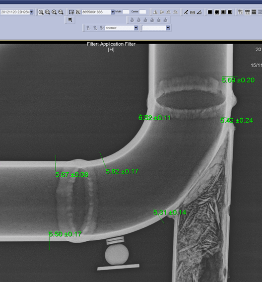
What was the difference between the 2 images which could provide such misleading information ? The first image was radiographed with a shortened source to film distance (due to access problems) and the isotope was positioned above the centre of the pipe. The second image had an increased source to film distance and the source was moved approx. 35mm and positioned directly above the side wall of the pipe (see example of set up below).
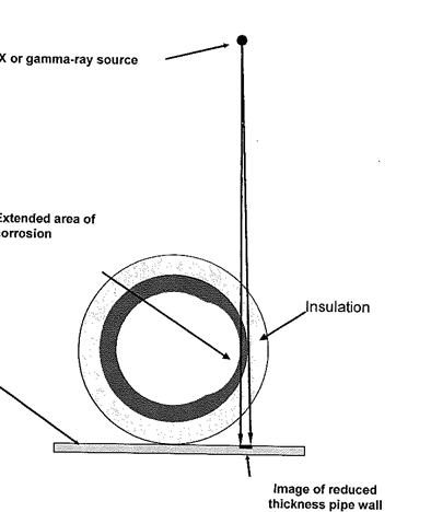
Learning from this – (i) Get your source to film distance right ( as far back as practical) and also where possible (ii) Position source directly above your area of concern. In this instance if you are not above your area of concern then you may get a misleading result.
In summary the tangential radiographic technique is only capable of measuring wall loss at positions close to the tangent position which depends on the position of the source and the detector.
